


Preventing Loss and Distortion - IMS 2026 Amphenol Workshop
At IMS 2026, SV Microwave joined forces with Amphenol Printed Circuits, Micro-Coax, Q Microwave, Times Microwave Systems, and XMA Corporation. This included multiple joint events, such as a booth, a happy hour, and an industry workshop.
This workshop discussed how to prevent loss and distortion. Read below to hear more about what our Principal Electrical Engineer, Evan Tarr, talked about, or watch the video below!
In Evan’s portion of the panel, he discussed how to carry the signal from the cable to the PCB, as many issues can arise during this transition.
There’s no one perfect solution for every issue, which is why SV has a variety of connectors and product lines tailored to different situations.
Full-Wave 3D Simulation Tools
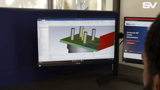
Complex systems are continuously pushing to higher frequencies. Full-wave 3D simulation tools like CST and HFSS greatly help our engineers and customers achieve high-performance designs. Encrypted models are available on our site for customers to download and load into their projects. This allows our customers to see the full performance while still obscuring our designs. If a customer doesn’t have the tools, know-how, or time, we are happy to create a fully formed footprint for them. A footprint contains the PCB's geometry and layout.
Solder vs. Solderless Connectors
One way to attach a connector to a PCB is with solder. While solder is commonly used, it can cause issues in reflow. Hand soldering can cause a messy board, shorts, and other performance issues.
The easiest way to avoid solder is to use solderless connectors. These provide an interference fit, as the center conductor sits slightly higher than the body of the connector. This will be gently pushed into the core and copper on the surface of the board. These are easy to install, and just takes a steady hand and a few screws.
While solderless connectors offer many benefits, they also have downsides. You don’t get the permanence of solder connectors, and they may not operate well under high shock and vibration.
Connector Angles
There are various angles for a connector to approach the board. Edge launch connectors are mounted to the edge of the PCB. The transmission line of an edge-launch connector is colinear with the axis of the PCB trace. This direct signal means it can operate at higher frequencies. However, there’s limited real estate on a board for these connectors, because there’s only so much edge.
Surface-mount connectors can be placed anywhere on the board, but the right-angle connection can greatly reduce your max frequency.
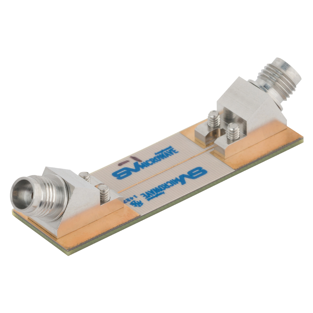
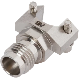
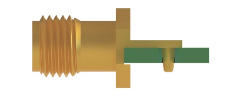
Our 30° Solderless PCB Compression Mount Connectors provide the best of both worlds. It sits on the surface of the board, but the 30-degree tilt is close enough that it gives you edge launch performance anywhere.
Air Gaps and the Edge of the Board
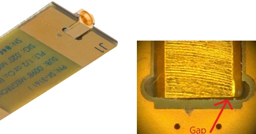
Getting a connector to the edge of the board sounds a lot easier than it is. If you don’t line the connector exactly up to the board, it creates an air gap. Even a gap as small as .015” can have a significant undesirable effect on RF performance, particularly in regard to return loss characteristics. Additionally, things can shift around in the reflow oven.
This is where our Edge-Lock RF PCB Connectors come into play. These connectors have tapered legs that pull them to the edge of the board and maintain their position throughout the reflow process.
Even if you use a regular connector and manage to keep it flush through the reflow process, something called copper-pullback can occur. Many FABs have copper pullback requirements, where they don’t want to run the copper to the edge of the board. This can be because when they go through the milling process, it can tear and cause various performance issues.
Since the copper isn’t run to the edge of the board, there is now an additional gap between the connector ground plane and the board ground plane. This can be just as bad for the signal integrity as the air gap.
That’s why we designed our Edge Launch Plus line. These connectors have a top half of the body that extends over the board. This allows the ground plane of the connector to make immediate contact with the ground plane of the board and bridge that gap.
Board-to-Board Connections
Often, the issue isn’t with board mounting; it’s the problems that come with board-to-board connections.
In an ideal world, the backplane and daughter card would line up perfectly. In reality, there are gaps and offsets.
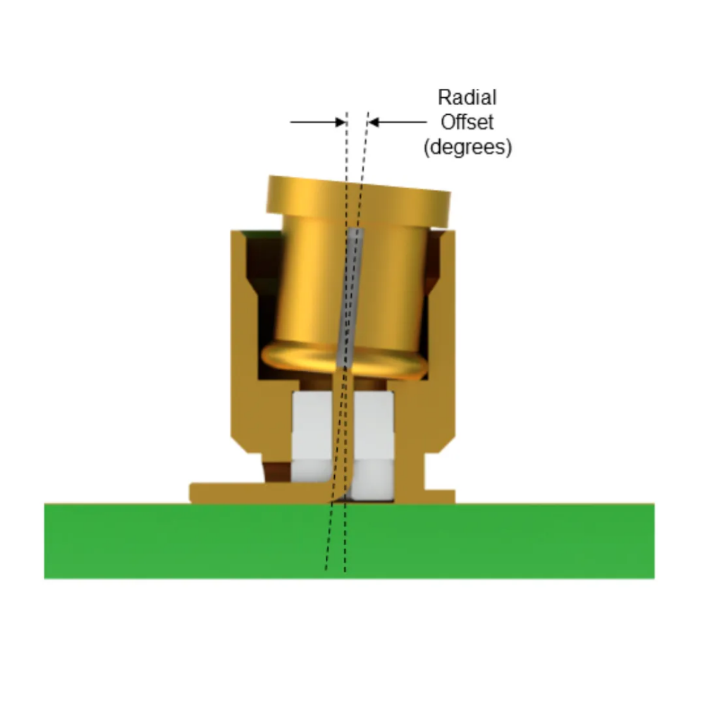
Once again, you’ll be dealing with air gaps. This comes down to offsets. This can be a radial offset if the center lines of the two boards are slightly offset. This will cause your connectors to be tilted, thus causing noise, distortion, and a harmful effect on the system's signal integrity.
Maintaining a tighter tolerance is difficult to handle in more complex systems. An airgap is caused at the interface of the connector on at least one side.
The most common and cheapest way to bring the two boards together is a fixed-length bullet. These are cheap and easy to use, but you won’t have any control over the gaps.

An axial offset also needs to be considered. This is the distance between the reference plane and the closest point of the bullet.
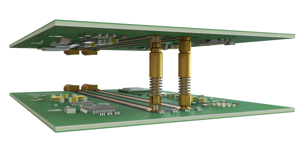
Another option is a compressible spring bullet. These have a range of compression over which they can operate and will fill the axial gaps and slightly improve the radial gaps. They also maintain a full 50 ohm line throughout the length of the connector. However, these come with added cost and complexity.

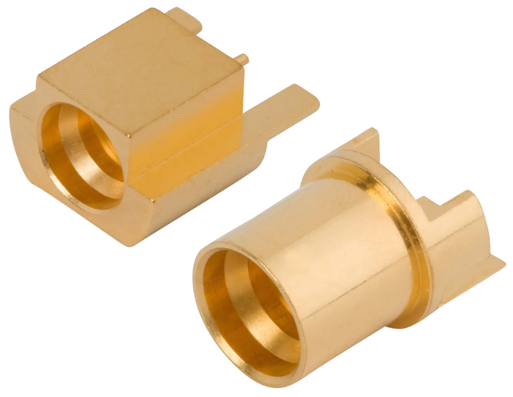
SV created our SMPM-XT RF Interconnects for lower frequency applications. These have an extended pin and socket contact to accommodate a greater degree of axial tolerance. These offer a secure and repeatable board-to-board connection up to 12 GHz. These are a cost-effective alternative to spring bullets.
Leakage and Shielding
As frequencies and power levels push higher, everything's getting denser in a small box. You no longer only have to worry about your individual connection, but what’s leaking out of it.
There are various kinds of transmission lines you can be launching to. If you’re going to a surface trace such as a CPW or microstripe, it’s inherently going to be a bit leaky amongst each other.
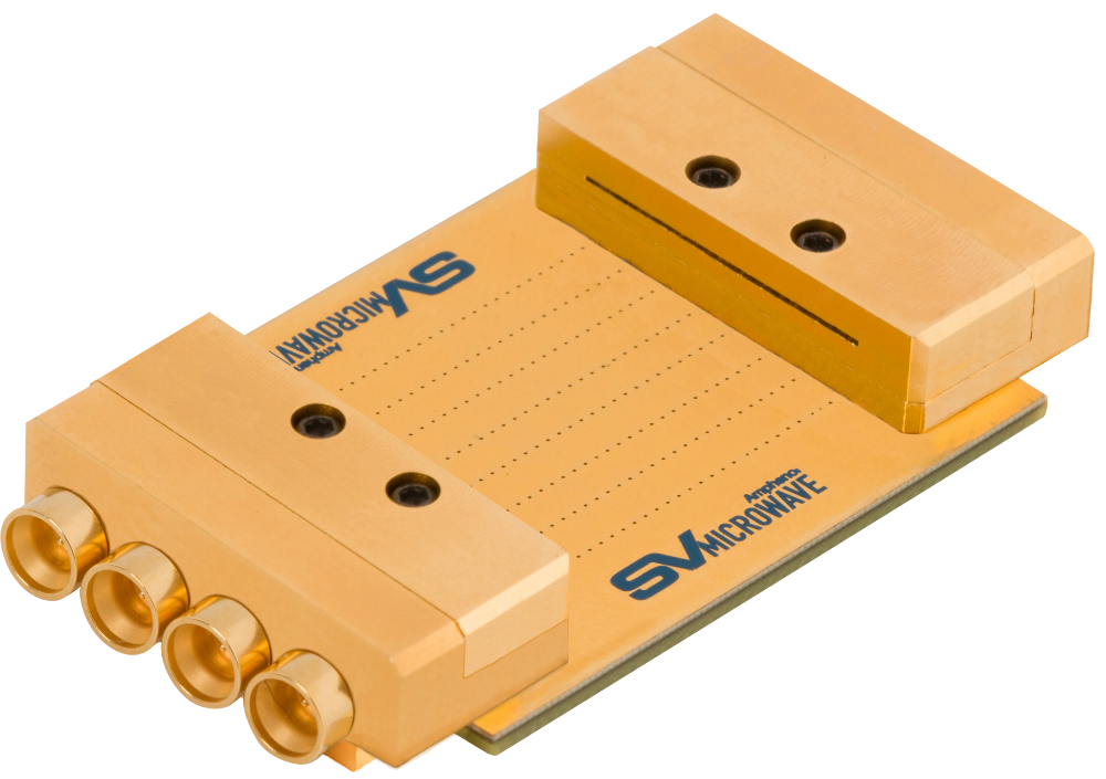
The current approach is typically to use gaskets or bespoke shielding, but this can be expensive and complex to install. Some connectors will handle this for you, like our Shielded Edge Launch Connectors. These connectors provide a built-in EMI shielded connector that gives up to 70dB of crosstalk isolation, preventing signal interference by isolating each of the different RF channels. The lid is removable, so you can still inspect your solder joint.
Want to learn more about SV’s recent launches? Check out our new product page.
recent releases
Preventing Loss and Distortion - IMS 2026 Amphenol Workshop
At IMS 2026, SV Microwave joined forces with Amphenol Printed Circuits, Micro-Coax, Q Microwave, Times Microwave Systems, and XMA Corporation. This included multiple joint events, such as a booth, a happy hour, and an industry workshop.
This workshop discussed how to prevent loss and distortion. Read below to hear more about what our Principal Electrical Engineer, Evan Tarr, talked about, or watch the video below!
In Evan’s portion of the panel, he discussed how to carry the signal from the cable to the PCB, as many issues can arise during this transition.
There’s no one perfect solution for every issue, which is why SV has a variety of connectors and product lines tailored to different situations.
Full-Wave 3D Simulation Tools
Complex systems are continuously pushing to higher frequencies. Full-wave 3D simulation tools like CST and HFSS greatly help our engineers and customers achieve high-performance designs. Encrypted models are available on our site for customers to download and load into their projects. This allows our customers to see the full performance while still obscuring our designs. If a customer doesn’t have the tools, know-how, or time, we are happy to create a fully formed footprint for them. A footprint contains the PCB's geometry and layout.
Solder vs. Solderless Connectors
One way to attach a connector to a PCB is with solder. While solder is commonly used, it can cause issues in reflow. Hand soldering can cause a messy board, shorts, and other performance issues.
The easiest way to avoid solder is to use solderless connectors. These provide an interference fit, as the center conductor sits slightly higher than the body of the connector. This will be gently pushed into the core and copper on the surface of the board. These are easy to install, and just takes a steady hand and a few screws.
While solderless connectors offer many benefits, they also have downsides. You don’t get the permanence of solder connectors, and they may not operate well under high shock and vibration.
Connector Angles
There are various angles for a connector to approach the board. Edge launch connectors are mounted to the edge of the PCB. The transmission line of an edge-launch connector is colinear with the axis of the PCB trace. This direct signal means it can operate at higher frequencies. However, there’s limited real estate on a board for these connectors, because there’s only so much edge.
Surface-mount connectors can be placed anywhere on the board, but the right-angle connection can greatly reduce your max frequency.
Our 30° Solderless PCB Compression Mount Connectors provide the best of both worlds. It sits on the surface of the board, but the 30-degree tilt is close enough that it gives you edge launch performance anywhere.
Air Gaps and the Edge of the Board
Getting a connector to the edge of the board sounds a lot easier than it is. If you don’t line the connector exactly up to the board, it creates an air gap. Even a gap as small as .015” can have a significant undesirable effect on RF performance, particularly in regard to return loss characteristics. Additionally, things can shift around in the reflow oven.
This is where our Edge-Lock RF PCB Connectors come into play. These connectors have tapered legs that pull them to the edge of the board and maintain their position throughout the reflow process.
Even if you use a regular connector and manage to keep it flush through the reflow process, something called copper-pullback can occur. Many FABs have copper pullback requirements, where they don’t want to run the copper to the edge of the board. This can be because when they go through the milling process, it can tear and cause various performance issues.
Since the copper isn’t run to the edge of the board, there is now an additional gap between the connector ground plane and the board ground plane. This can be just as bad for the signal integrity as the air gap.
That’s why we designed our Edge Launch Plus line. These connectors have a top half of the body that extends over the board. This allows the ground plane of the connector to make immediate contact with the ground plane of the board and bridge that gap.
Board-to-Board Connections
Often, the issue isn’t with board mounting; it’s the problems that come with board-to-board connections.
In an ideal world, the backplane and daughter card would line up perfectly. In reality, there are gaps and offsets.
Once again, you’ll be dealing with air gaps. This comes down to offsets. This can be a radial offset if the center lines of the two boards are slightly offset. This will cause your connectors to be tilted, thus causing noise, distortion, and a harmful effect on the system's signal integrity.
Maintaining a tighter tolerance is difficult to handle in more complex systems. An airgap is caused at the interface of the connector on at least one side.
The most common and cheapest way to bring the two boards together is a fixed-length bullet. These are cheap and easy to use, but you won’t have any control over the gaps.
An axial offset also needs to be considered. This is the distance between the reference plane and the closest point of the bullet.
Another option is a compressible spring bullet. These have a range of compression over which they can operate and will fill the axial gaps and slightly improve the radial gaps. They also maintain a full 50 ohm line throughout the length of the connector. However, these come with added cost and complexity.
SV created our SMPM-XT RF Interconnects for lower frequency applications. These have an extended pin and socket contact to accommodate a greater degree of axial tolerance. These offer a secure and repeatable board-to-board connection up to 12 GHz. These are a cost-effective alternative to spring bullets.
Leakage and Shielding
As frequencies and power levels push higher, everything's getting denser in a small box. You no longer only have to worry about your individual connection, but what’s leaking out of it.
There are various kinds of transmission lines you can be launching to. If you’re going to a surface trace such as a CPW or microstripe, it’s inherently going to be a bit leaky amongst each other.
The current approach is typically to use gaskets or bespoke shielding, but this can be expensive and complex to install. Some connectors will handle this for you, like our Shielded Edge Launch Connectors. These connectors provide a built-in EMI shielded connector that gives up to 70dB of crosstalk isolation, preventing signal interference by isolating each of the different RF channels. The lid is removable, so you can still inspect your solder joint.
Want to learn more about SV’s recent launches? Check out our new product page.